Installation Ready AC Power
Installation and Startup
Master Module Installation
The master module includes:
- A photovoltaic module
- DC/AC conversion electronics
- Male/female single-phase AC connections to link multiple master modules and connect to the AC grid
- Male/female DC connectors (MC4) to connect slave modules
The DC connections of the slave modules are directly connected to the master module, eliminating the risk of high DC voltage. The master module is mounted on brackets suitable for the installation context.
Installation must comply with local regulations.
Slave Module Installation
The slave module(s) are positioned next to the master and connected to it via the appropriate cables mounted on the master.
Do not use an AC circuit breaker to protect the circuit dedicated to the master module. Small breakers (5~30mA) are not designed to handle backfeed and could be damaged.
Necessary Tools and Components Not Included in the Kit
- An AC junction box
- Brackets for photovoltaic modules suitable for the installation context
- Screws and fittings required for mounting the brackets
- Washers and conductors for proper grounding
- Screwdrivers
- Torque wrenches
Phase 1 - Install the AC Junction Box
- Install an appropriate junction box in an accessible location near the photovoltaic system (usually at the end of the AC branches).
- Insert the AC network cable into the junction box using a strain relief fitting.
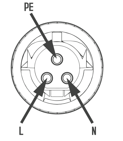
- Wire the AC connector: L - red; N - black; PE - yellow/green.
- Connect the circuit from the AC junction box to the utility interconnection point.
Phase 2 - Mount the Modules on the Fixing Brackets
After positioning and securing the most suitable fixing structures for the context, position and secure the modules to them.
Phase 3 - Prepare for Parallel Connection of Master Modules
In case of parallel connection, remove the plugs from the master modules, except the one sealing the AC line.
Phase 4 - Connect the Modules in Parallel
After positioning and securing the modules, connect the master modules in parallel using the appropriate male/female AC connectors.
Phase 5 - Connect the Master Module to the Slave Module(s)
Only after connecting the AC branches and securing the uncovered side with the cap, connect the MC4 connectors of the master to the slave modules.
When connecting the DC cables, if AC power is already available, the LED on the back of the master module will start flashing red and will begin operation after 60 seconds. If AC power is not available, the LED will flash red quickly three times every second until AC is connected.
System Startup Instructions
- Turn on the switch for each AC branch.
- Turn on the main network switch. The system will begin producing energy after a one-minute wait.
- The master module's LED will start flashing red. Then it will flash blue. The blue color indicates energy production. The faster it flashes, the higher the energy production.
- Configure the internal Wi-Fi module following the appropriate manual.
- The master module will start sending performance data via Wi-Fi every 5 minutes. This allows the user to monitor production data for each master module via a specific website or app.
When AC power is applied but the master module is not started, about 0.1A current and 25W power per master module may be measured by a meter. This is reactive power, not consumption from the grid.
Need assistance?
Request Support